
Application-led system planning
What Are C&I Energy Storage System Use Cases? 4 Examples
Compare peak shaving, solar self-consumption, backup reserve and industrial microgrid examples—and see how each objective changes power, energy, controls and equipment format.
What are the main C&I energy storage system use cases?
The main C&I energy storage system use cases include peak shaving, solar self-consumption, backup reserve, capacity support, EV charging and industrial microgrids. The four scenarios below are illustrative engineering examples—not claims about completed customer installations. Each one converts an operating problem into screening power, energy, control and equipment inputs; final sizing still requires measured site data and project-specific engineering.
Selection framework
Start with the operating objective, not the product label
A commercial or industrial site rarely buys storage only because a cabinet has a convenient kWh number. The project begins with a measurable constraint: a demand peak, unused solar production, a critical-load autonomy target, an expansion limit or a source-priority requirement.
Translate that problem into four linked questions before comparing equipment:
How many kW must move?
Define the peak reduction, critical load, charging limit or plant dispatch target at the agreed electrical boundary.
For how long?
Use the load or generation profile to calculate usable kWh, then add the approved reserve, loss and ageing basis.
What triggers dispatch?
Document metering, tariff periods, export limits, reserve SOC, transfer logic and source priority.
Where does responsibility end?
Separate the BESS from transformer, switchgear, civil work, communications, commissioning and grid studies.
Illustrative case 01
Peak shaving at a manufacturing site
Assume a plant wants to reduce a recurring two-hour demand peak by 100 kW. The first screening requirement is 100 kW of continuous AC discharge and 200 kWh of usable AC energy. The quotation must then account for reserve SOC, conversion losses, auxiliary consumption, ambient derating and the end-of-life guarantee.
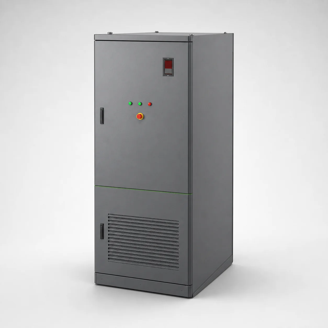
A documented 105 kW / 233 kWh cabinet may be a starting configuration, but 233 kWh is rated battery energy rather than a guaranteed 200 kWh at the AC boundary. Confirm the dispatch window using the peak-shaving sizing guide.
Illustrative case 02
Solar self-consumption for a commercial campus
Suppose interval data shows 80 kW of repeatable midday PV surplus for 2.5 hours, while the evening load can absorb the energy. The starting opportunity is about 200 kWh before charging losses, export-control behavior and weather variability are considered.
The 125 kW / 261.2 kWh cabinet offers additional power headroom and a 400 V interface. Selection depends on the PV meter location, maximum charging power, export rule, evening discharge target and the minimum reserve retained for other duties.
Use time-series PV data
- Separate curtailment from genuine surplus
- Check seasonal and cloudy-day variation
- Confirm the meter and export-control point
Prove an energy sink exists
- Map evening and peak-period demand
- Define charging and discharge limits
- Avoid sizing from annual totals alone
Illustrative case 03
Critical-load reserve plus daily demand control
A site with 200 kW of prioritized loads and a two-hour autonomy target begins with 400 kWh of usable backup energy. If the same battery also performs daily peak shaving, the EMS must preserve the backup reserve and limit daily dispatch to the energy remaining above that floor.
The documented 250 kW / 522.5 kWh cabinet uses two 125 kW PCS blocks and a 400 V interface. It is a screening candidate only after the protected-load schedule, transfer device, motor starting behavior, islanding method and restart sequence are defined.
Do not allocate the same kWh simultaneously to daily savings and emergency autonomy. The control philosophy must state which objective has priority.
Illustrative case 04
Plant-level renewable firming and microgrid dispatch
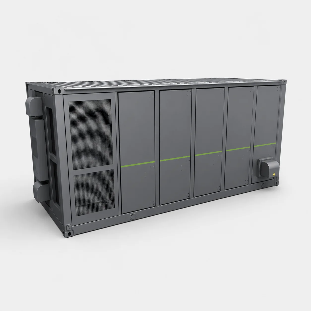
Larger industrial projects may require megawatt-scale charge and discharge, multiple battery strings, a centralized service layout and a medium-voltage interface. The documented 1.25 MW / 3.354 MWh container BESS combines nine LFP strings with a 690 V PCS stage and a project-side target of 10 kV through step-up equipment.
This configuration has an approximate rated energy-to-power ratio of 2.68 hours. The actual project still needs a single-line diagram, transformer and switchgear scope, fault level, protection study, plant EMS/SCADA protocol map, source priority and acceptance scenarios.
Scenario comparison
Different use cases create different starting configurations
| Use case | First sizing input | Starting platform | Critical evidence |
|---|---|---|---|
| Peak shaving | Target kW and peak duration | 105 kW / 233 kWh cabinet | Interval load profile and EMS demand-limit test |
| Solar self-consumption | PV surplus and evening load | 125 kW / 261.2 kWh cabinet | PV/load time series, export rule and meter map |
| Backup plus demand control | Critical-load kW and autonomy | 250 kW / 522.5 kWh cabinet | Protected loads, transfer logic and reserve SOC |
| Industrial microgrid | Plant dispatch and point of connection | 1.25 MW / 3.354 MWh container | SLD, protection, transformer scope and control hierarchy |
Use the kW vs kWh guide to separate power from energy and the cabinet vs container guide to compare equipment formats.
Quotation inputs
Turn the selected use case into a comparable RFQ
Send the site country, grid voltage, interval load and generation data, operating objective, critical-load list, required duration, ambient range, footprint, transport access, communication protocols and responsibility boundary. State whether the requested energy is rated DC energy or guaranteed usable AC energy.
Use the industrial BESS quotation scope and load-profile guide so every supplier receives the same assumptions.
All values on this page are screening examples. Final configuration and guarantees must be stated in approved project drawings, datasheets, control documents and acceptance procedures.
Buyer questions
Frequently asked questions
What are the main C&I energy storage system use cases?
Common starting objectives include peak shaving, solar self-consumption, backup reserve, capacity support, EV charging and microgrid operation. Each objective produces a different power, energy, control and acceptance-test requirement.
Is a use-case example the same as a completed customer case study?
No. The scenarios on this page are illustrative engineering examples built around documented product ratings. They do not claim a completed installation or guarantee project performance.
Can one battery serve peak shaving and backup at the same time?
It can support both objectives only when the EMS reserves sufficient state of charge for backup and the project accepts the remaining energy available for daily dispatch.
Which data is needed before selecting a C&I BESS?
Provide interval load and generation data, grid voltage, tariff periods, critical loads, required autonomy, ambient conditions, point of connection and the project responsibility boundary.
When should a project move from cabinets to a container BESS?
Consider a container when the required power or energy exceeds the practical cabinet block, when medium-voltage step-up equipment is required, or when centralized service, transport and fire layouts fit the site better.
Turn the use case into measurable inputs.
Power, energy, control priorities and project boundaries must be written before selecting the final equipment.