
Long-duration containerized BESS
1.725 MW / 5.016 MWh Container BESSFive megawatt-hours configured for energy-led dispatch.
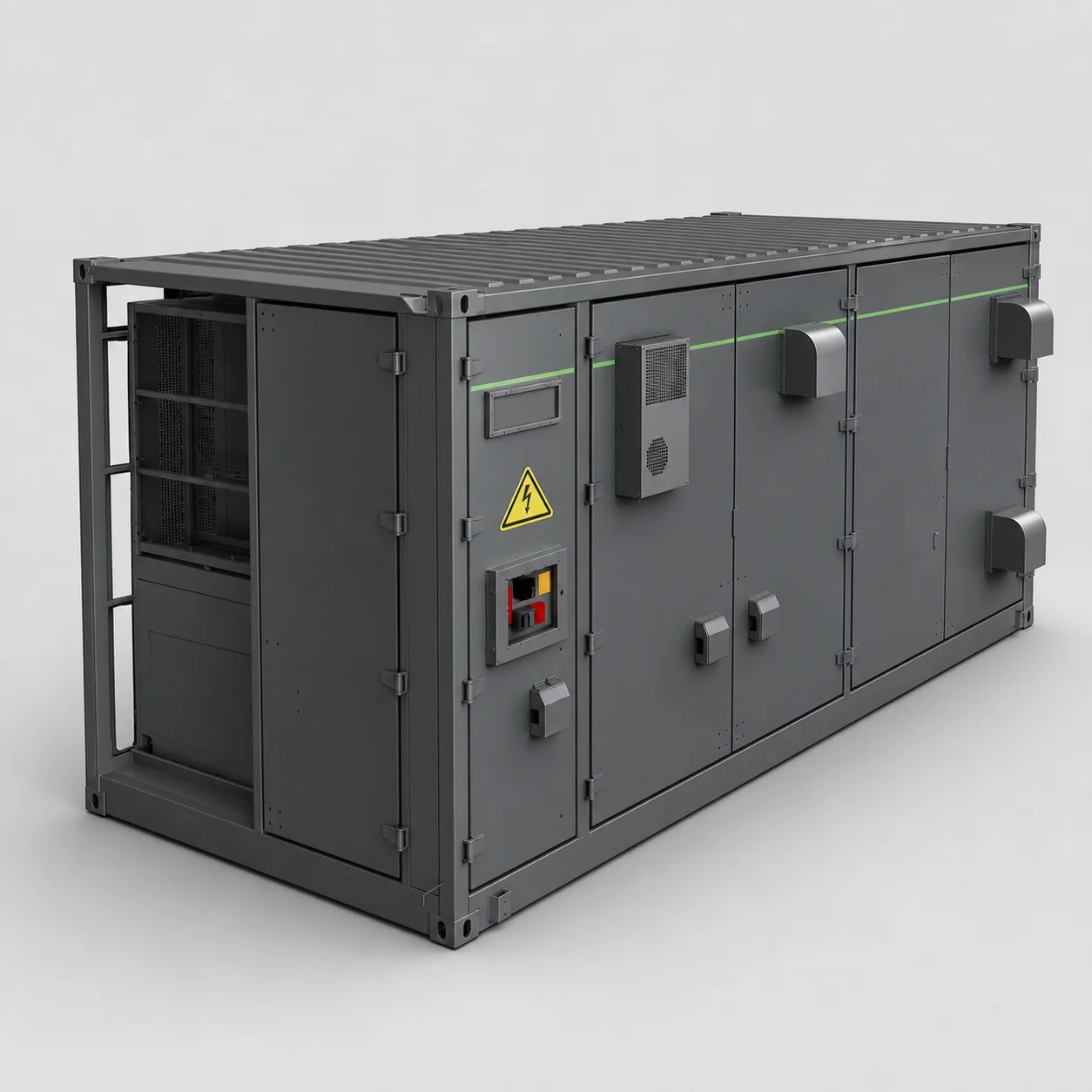
A 12-string, 5.016 MWh LFP container matched with a 1.725 MW PCS stage for approximately 2.91 hours of rated duration.
Application fit
Start with the operating duty.
This configuration uses twelve 314 Ah LFP strings to deliver 5.016 MWh at 1331.2 V nominal DC. A 1.725 MW PCS stage creates a nearly three-hour rated platform for projects where energy duration is prioritized over maximum short-window power.
Open the RFQ input checklistIntegrated architecture
Four layers form the starting platform.
The commercial scope still needs a project responsibility matrix covering every external interface.
Battery strings
Twelve LFP strings arranged as 12P416S provide 5.016 MWh rated energy.
DC collection
String-level protection and high-voltage collection feed a common PCS interface.
PCS and MV boundary
A 1.725 MW, 690 V PCS stage is coordinated with the project step-up design.
Container systems
BMS, EMS, liquid cooling, fire protection and communications support plant operation.
Technical specifications
Documented configuration data.
Values are taken from the supplied manufacturer specification. Final purchase, installation and acceptance must use the approved project datasheet, drawings and test documents.
| Group | Parameter | Documented value |
|---|---|---|
| Battery | Cell chemistry and format | LFP, 3.2 V / 314 Ah |
| Battery | Rated energy | 5016 kWh |
| Battery | Nominal DC voltage | 1331.2 V |
| Battery | DC voltage window | 1040-1500 V |
| Battery | String arrangement | 12P416S |
| PCS | Rated AC output | 1725 kW |
| PCS | PCS AC voltage | 690 V |
| PCS | Maximum DC current | 1897 A |
| PCS | Rated frequency | 50 Hz |
| Project | Target project-side interface | 10 kV through PCS step-up unit |
| System | Charge/discharge rate | Up to 0.33C |
| System | Base container dimensions | 6500 x 2700 x 2950 mm |
| System | Service/interface envelope | 6700 x 3200 x 2950 mm |
| System | Approximate weight | 44 t |
| System | Communications | RS485 / CAN / Ethernet |
| Environment | Altitude | Up to 2000 m |
| Environment | Enclosure | IP54; C3 corrosion protection |
| Environment | Operating temperature | -20 C to 55 C |
| Environment | Relative humidity | 0-95%, non-condensing |
| Thermal | Cooling | Intelligent liquid cooling |
| Safety | Fire suppression | Perfluorohexanone system |
Scope boundary
Separate product from project.
A comparable quotation makes included equipment and external responsibilities explicit.
Starting equipment scope
Documented platform
- Twelve-string 5.016 MWh battery container
- String monitoring and high-voltage DC collection
- BMS and EMS control layers
- Liquid cooling and auxiliaries
- Fire detection and suppression system
- Internal communications and local controls
Project boundary
Confirm before quotation
- 1.725 MW PCS and transformer package boundary
- MV switchgear, relay and grid-study requirements
- Station auxiliary-power architecture
- Foundation, crane plan and delivery route
- SCADA, dispatch and cybersecurity requirements
- FAT witness points and commissioning tests
Buyer questions
Resolve these points before ordering.
Use the answers to narrow the design; use the final project documents to release the order.
Why choose 1.725 MW instead of 2.5 MW for the same energy?
The 1.725 MW version provides a lower C-rate and about 2.91 hours of rated duration, which suits energy-led dispatch. The 2.5 MW version targets higher power and roughly two-hour duty.
Can this system support frequency services?
PCS and EMS capability must be matched to the grid code, response-time requirement, SOC management strategy and warranty duty cycle before frequency-service claims are confirmed.
Does the listed weight include the step-up transformer?
The approximate 44 t figure refers to the documented battery container. Confirm PCS, transformer and switchgear weights separately in the project equipment schedule.
What determines the final site footprint?
The equipment envelope, service corridors, fire separation, transformer and switchgear locations, cable trenches, turning radius and crane outriggers all affect the final layout.
Buyer engineering guides
Check the assumptions around this configuration.
Connect the product data to measured demand, electrical design, safety evidence and quotation scope.
Compare adjacent configurations
Continue the product review.
Compare power, duration, interface and project boundary before selecting a starting platform.
Product quick RFQ
Match this configuration to the real site.
Send the country, operating target and the first project requirements. The product title and source page are attached automatically.