
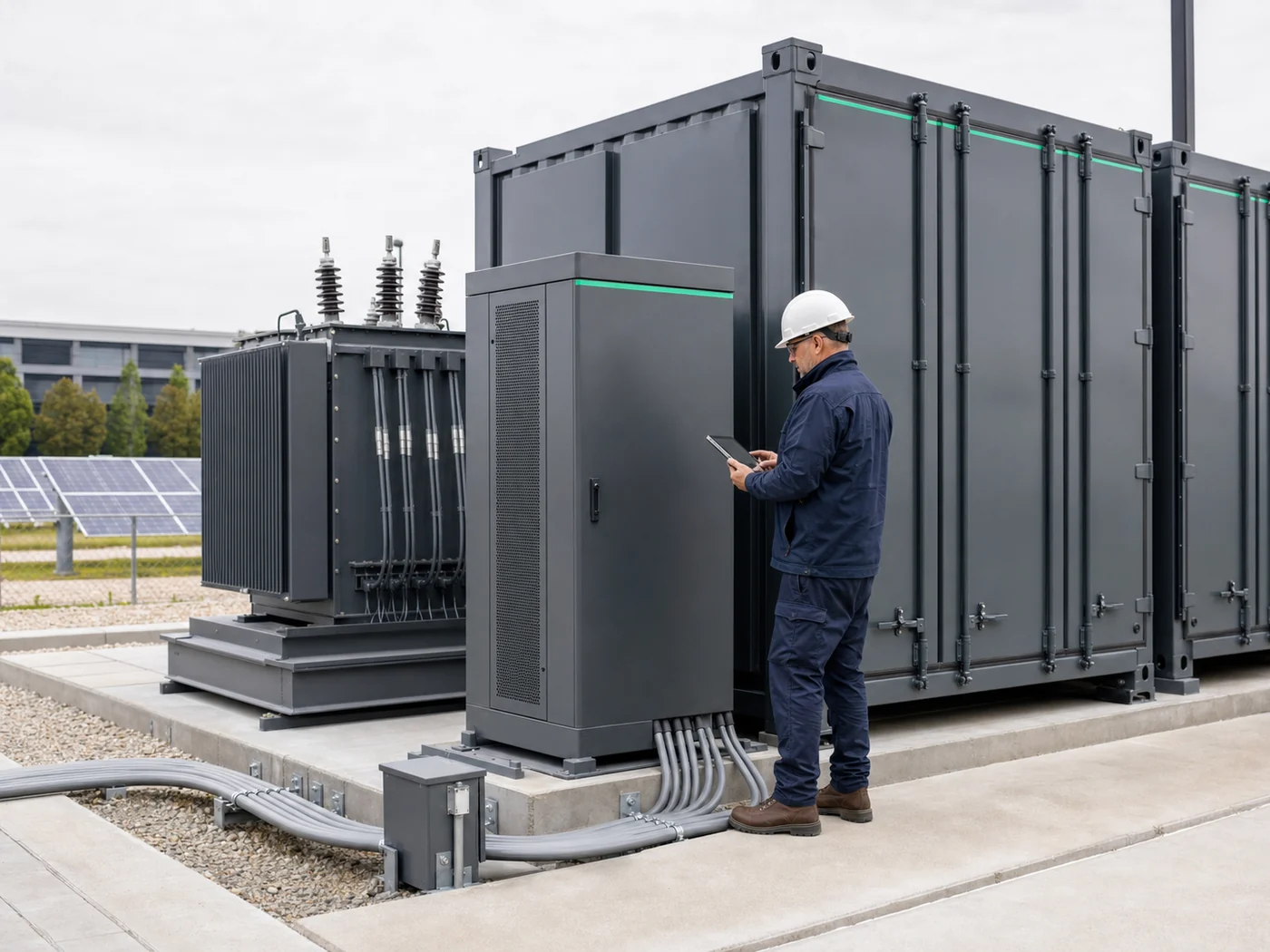
Engineering process
From measured inputs to a frozen project boundary.
A disciplined process matches the documented product platform to load target, voltage, PCS behavior, site conditions, safety scope and supplier responsibility.
Six-step workflow
Reduce ambiguity before ordering.
Each step closes a different technical or commercial boundary before final quotation.
Operating requirement
Clarify peak shaving, PV self-consumption, backup, microgrid, UPS or reserve duty.
Measured site data
Use interval load, PV generation, charger profile, critical-load and grid information.
Electrical architecture
Resolve cabinet or container format, PCS, DC window, transformer, STS/ATS and protection.
Product configuration
Match a documented platform to power, energy, voltage, ambient, fire and service constraints.
Compliance and evidence
Confirm jurisdiction, required certificates, drawings, fire documents, transport and FAT plan.
Frozen project boundary
Issue the project datasheet, responsibility matrix, exceptions, schedule and commissioning scope.
Design gates
Every gate produces a reviewable output.
Engineering is complete enough for quotation only when inputs, assumptions, decisions and evidence are visible.
| Gate | Buyer provides | Engineering resolves | Output |
|---|---|---|---|
| 1. Requirement | Business target, tariff, outage objective | Operating modes, reserve and success criteria | Basis of design |
| 2. Site data | Load curve, PV/charger data, grid and ambient | Required kW, usable kWh and derating | Sizing record |
| 3. Architecture | Connection voltage, SLD, transformer and generator | AC/DC topology, PCS, STS/ATS and protection | Concept single-line |
| 4. Configuration | Footprint, access, climate and preferred format | Model, battery window, cooling and fire interfaces | Project datasheet |
| 5. Evidence | Jurisdiction, buyer standards and inspection plan | Document list, compliance gaps and FAT procedure | Submittal register |
| 6. Commercial freeze | Incoterm, schedule, site works and support | Included, excluded and optional responsibilities | Technical offer and responsibility matrix |
Operating model
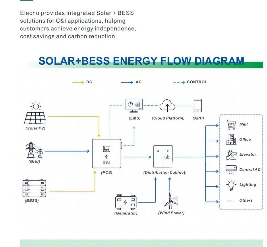
The load curve decides more than the product brochure.
Peak shaving, valley filling, PV capture and backup reserve require different PCS power, usable energy and dispatch logic.
Architecture boundary
Separate the product platform from site scope.
The technical offer should show which items are integrated, project-configured or supplied by others.
| Platform | Documented configurations | Product-side basis | Project-side confirmation |
|---|---|---|---|
| C&I cabinet | 105/233, 125/261.2, 250/522.5 | Integrated 400 V PCS, BMS, EMS, liquid cooling and fire protection | Site transformer, switchgear, cables, civil works and local approvals unless included |
| Container BESS | 1250/3354, 1725/5016, 2500/5016 | Battery container plus PCS step-up architecture toward a 10 kV connection | MV protection, substation boundary, civil works and grid-study scope |
| PV-storage-diesel | 100/233 hybrid cabinet | PCS, 100 kW DCDC/MPPT, 200 kW STS, BMS, EMS, cooling and fire protection | PV array, generator, upstream/downstream switchgear and site integration |
| Sodium-ion UPS DC | 219.24 kWh DC cabinet | Battery string, BMS, EMS, liquid cooling, fire protection and DC breaker | UPS, redundancy, DC protection coordination and autonomy validation |
Delivery evidence
Ask for documents before final payment.
Make the evidence visible in the quotation and purchase scope before production begins.
Drawings and interfaces
Single-line diagram, layout, cable boundary, communication map and protection settings.
FAT and serial records
Startup, alarm, E-stop, communication and ordered-equipment evidence.
Shipping and commissioning
Packing, certification, manuals, parameter files and commissioning responsibility.
Engineering reference
Resolve electrical, safety and input evidence.
These three guides close recurring design gaps before drawings, FAT scope and quotation assumptions are frozen.
400 V vs 690 V BESS
Review current, cable, switchgear, transformer and AC interface implications.
Read guideBESS fire protection documents
Check design basis, detection, suppression, alarms, emergency stop and FAT evidence.
Read guideLoad profile for a BESS quotation
Prepare interval demand, tariffs, PV, generators, critical loads and operating schedules.
Read guideFactory acceptance
Test the ordered configuration and its control behavior.
FAT evidence should connect the quotation, serial records, operating logic and shipment condition.
| FAT group | Verify | Keep as evidence |
|---|---|---|
| Identity and build | Nameplates, model, serial numbers, battery/PCS configuration and visible workmanship | Photo register and as-built bill of materials |
| Electrical function | Startup, charge/discharge command, metering, breaker status and auxiliary power | Recorded values and signed test sheet |
| Controls | BMS–PCS–EMS communications, remote commands, alarms and event logging | Protocol map, screenshots and alarm record |
| Safety | Emergency stop, door/interlock status, detection and suppression interfaces | Cause-and-effect evidence |
| Shipment | SOC, isolation, packing, accessories, documents and transport restraints | Packing list and pre-shipment photo record |
Resolve the project boundary before it becomes a field problem.
Send the operating objective, load and generation data, grid single-line, site conditions, target platform and required delivery evidence.